The Peavey Ultra was first made in the early 90’s. The updated version, the Ultra Plus was made from 1995 – 2001.
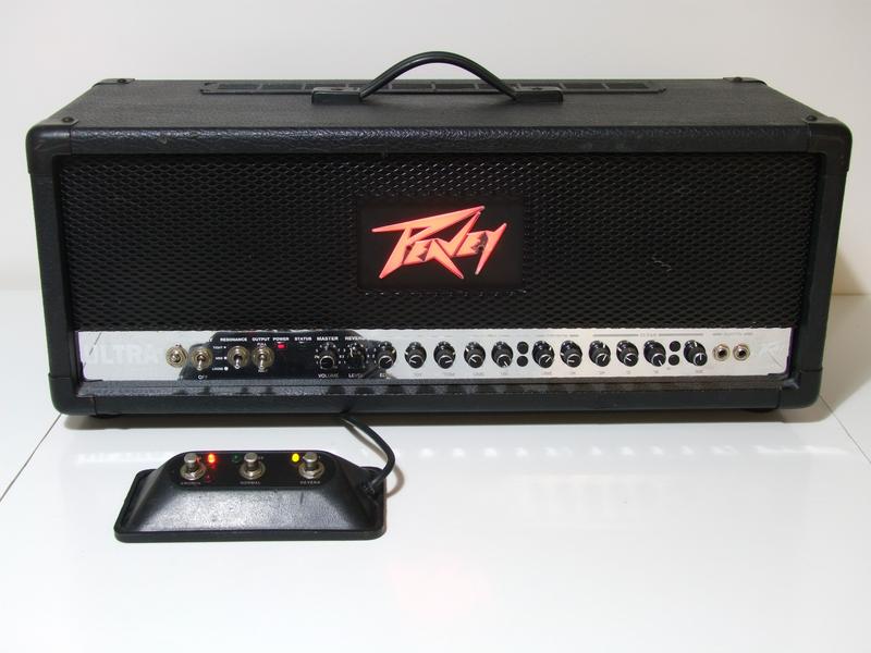
- In-depth review of the amp with pictures
- Additional reviews that are shorter but give alternating opinions
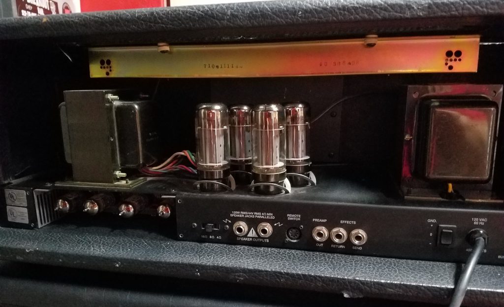
- Pictures of the inside of a Peavey Ultra Plus (Tubes & PCB)

Download the Peavey Ultra Plus manual
Peavey Ultra Plus Mods
NOTE – This is an untested mod from a forum: If you want to change the tone of the amp check out the coupling cap between the gain stages(C14 / .0010uF on rockmaster unsure on the Ultra) feeding the third tube stage (V2a). It has a frequecy rolloff of 340hz, which means it notches out everything below 340hz. Try a .0022uF in its place, this should give you a rolloff of about 154hz letting more low mid bass through. This made a huge difference in my rockmaster. Also look at the bypass cap on V2a (C17/.47uF on RM). It creates a pass frequecy of 450hz. Everything below 450hz is cut. Try using a 1.0uF which will give you around 205hz. These two mods really took the honk out of the rockmaster, gave it a great boost in the low mids (mesa land) and for less than $10 dollars in parts and less than an hour of work it was well worth it.
Another untested mod from a poster who wrote: “I can report excellent results from the following mods” And the following:
1) swapping out the C76 coupling cap after V1b from the (overly shrill) 1nf -> 2.2nf film (Xicon 1431-6222K at Mouser, $0.41)
2) changing the parallel C75 470pf/R502 470k before V2a to 2.2nf/470k (Xicon 1431-6222K at Mouser, $0.41)
3) upping the V1b C35 0.47uf EL cathode bypass cap to 1uf film (Kemet R82DC4100CK60J at Mouser $0.43)
These work great on the Ultra+ heads and Ultra 212 (which have Ultra+ labeled boards internally) huge low end bloom and no midrage “cocked wah” honk in the mids,
The older Ultras (PAG Ultra 120) have a few different values in the preamp;
A) 2 x 0.47uF cathode bypass caps
B) no parallel 470pF cap to R502
C) C5 on main board is 820pF ceramic and putting them to Ultra+ values sound better to my ears and even better when modded as above. Remember the HC review “trick” peg all controls EXCEPT active EQ which is set to FULL CUT (-15db) and then carefully dial up EQ for extreme PA dist! Yeow! hell on wheels!
Also, word is the Soviet 6P3S-E servo tube with the small “coin/wafer” base sound fantastic in this and other 6L6 amps,
Peavey Ultra Plus Resonance Circuit
The following information was consolidated from Redplate City. The Peavey Ultra Plus resonance control is a three-position switch type, labeled TIGHT, MED and LOOSE. The filter setting are preset at the factory. There’s no adjustable POT like some resonance controls use.
One fact is known from the start–the Ultra and the Ultra Plus are VERY similar in nearly all aspects. The point on the phase inverter–where the feedback is routed–and the transformer tap (the 8 ohm secondary) are identical in both amps. The Ultra Plus merely adds some addtional components between the two points.
Off to the web to research. First off, it looks like Peavey went to some length to hide / obfuscate the feedback loop circuit. There are versions of the Ultra Plus schematic that omit both the feedback control schematic and it’s small circuit board, too. There’s also a little note on the “sanitized” schematic how “THIS CIRCUITRY IS PROTECTED BY U.S. PATENT” 5,197,102 patent seems somewhat applicable. But I don’t see anything groundbreaking there (i.e., anything unique) that applies to the Ultra Plus resonance circuitry.
Schematic with the NFB loop filter intact:
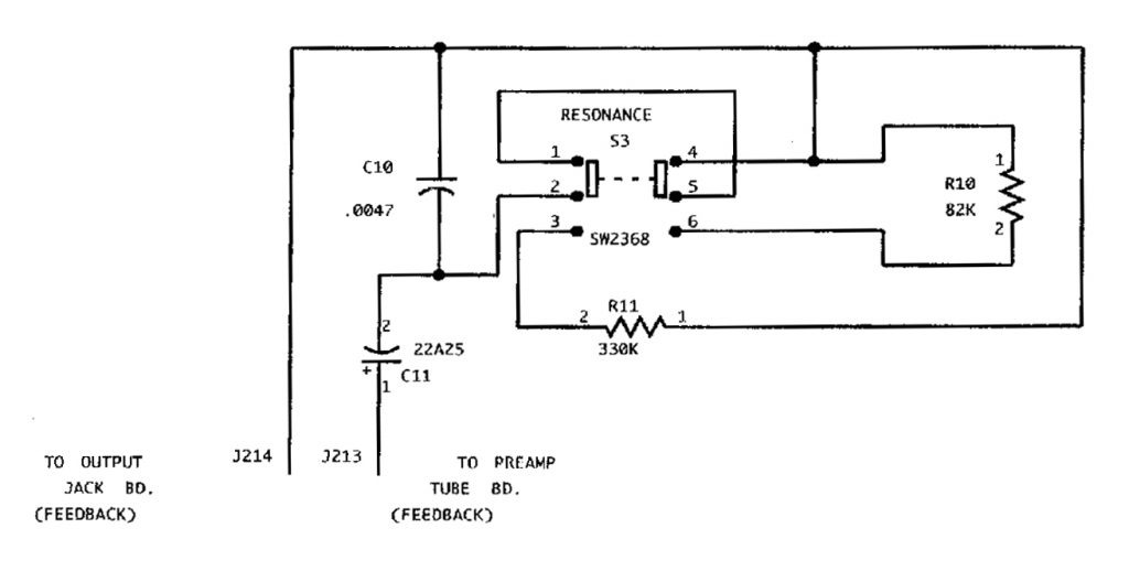
It’s not a complicated design. And not that different from other NFB filters, such as the Fender Bassman AC568 for one, and several older Gibson amps.

But the switch diagram and the switch description are confusing. The switch, tagged S3, certainly looks like a standard DPDT switch on the schematic, but the parts list says SPTT (or Single Pole Triple Throw). The drawing is not a single pole switch in the normal sense. Moreover, it doesn’t “decode” correctly as a standard DPDT switch, either. That is, it wouldn’t function correctly using a standard switch. After several failed sketches and more research, I found the best candidate for the switch; a DPDT on-on-on switch, where the contacts on each pole are opposed in the middle position. It works like the diagram on the right.
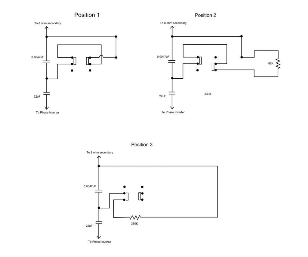
Position 1) bypasses C10
Position 2) parallels C10 with an 82K resistor
Position 3) parallels C10 with a 330K resistor
(there’s also a 68K resistor between the filter and the PI, as noted below..)
Note that the Peavey Ultra (and the Plus) has a fixed feedback resistor of 68K in the loop between the transformer and the phase inverter (and the Ultra Plus inserts the resonance control between the resistor and the transformer), while the 5150 has a 39K resistor between the transformer secondary and the filter circuitry, probably due to the addition of the Presence control–or the different sonic characteristics of the amp itself.
Peavey Ultra Footswitch Schematic
Link to footswitch schematic
Peavey Ultra Advertisements